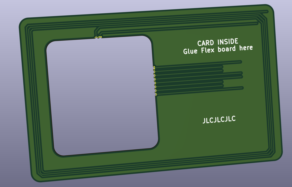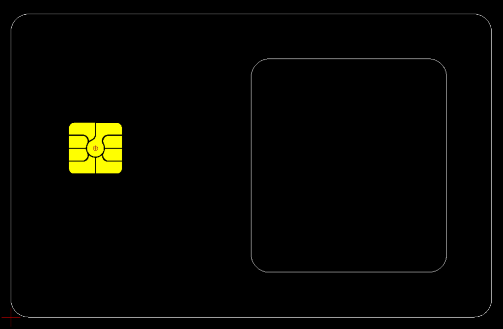
Contact Module
M2 ISO 7816 Smart Card Module
Comming up with a shape I like
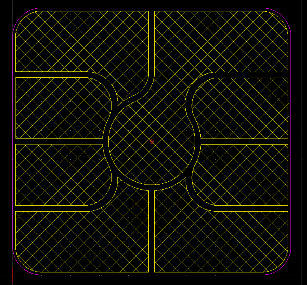
https://en.wikipedia.org/wiki/ISO/IEC_7810
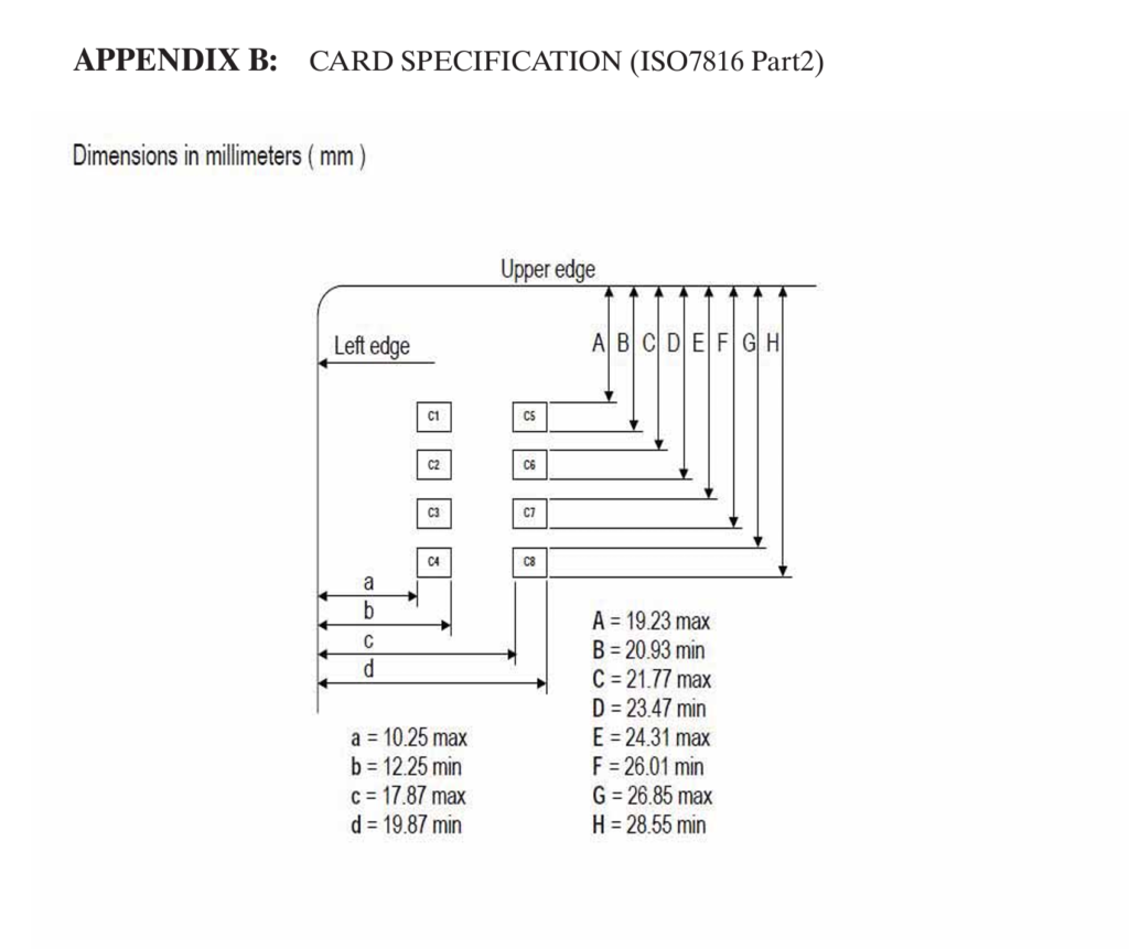
Placement of the pin contacts
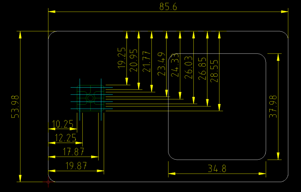
The Concept
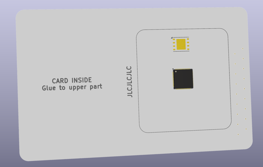
Using a dual sided 0.6mm FR4 ENIG board to create the contacts with an interiour slot for componets. Top side has no copper other than the pads
VIA’s inside the contact to the bottom layer and then using a 0.12mm Flex board glued to the back, this will complete the the card to create a reasonable thickness of 0.72mm
Then exposed flex area will allow for functional parts. Later it can be expoxied in.
Something like a rpi pico chip should fit in the 0.6 profile area not exceeding the card ISO spec of 0.76mm +/- 0.08mm
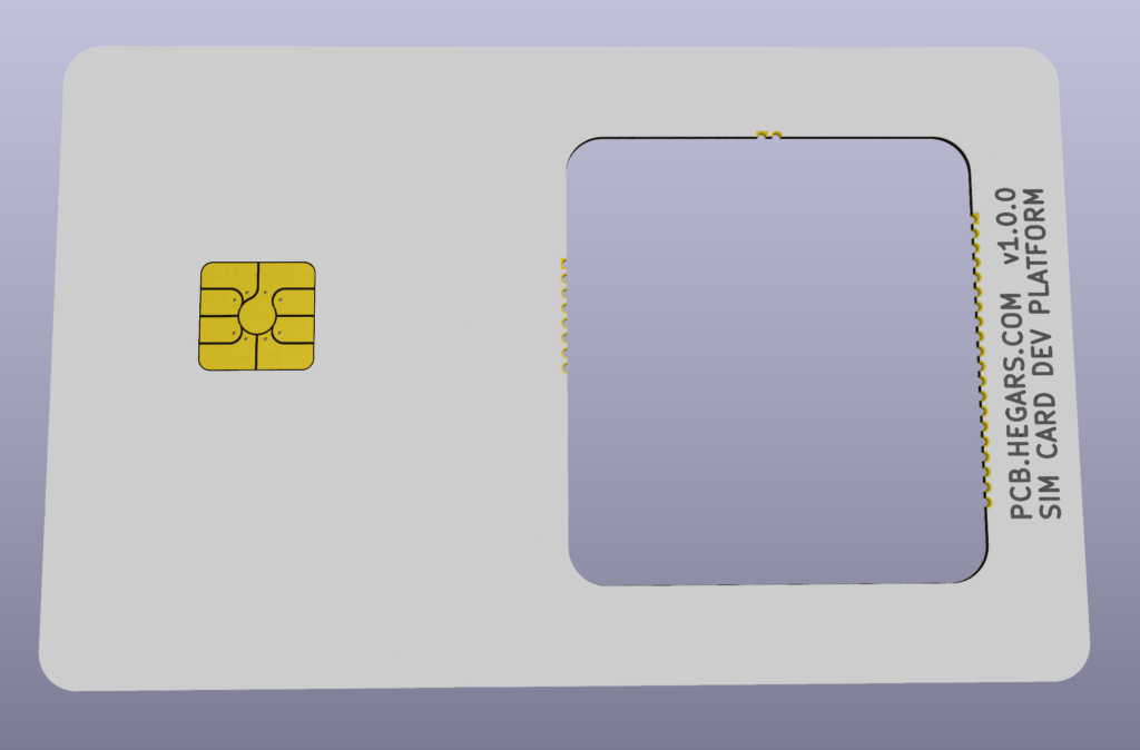
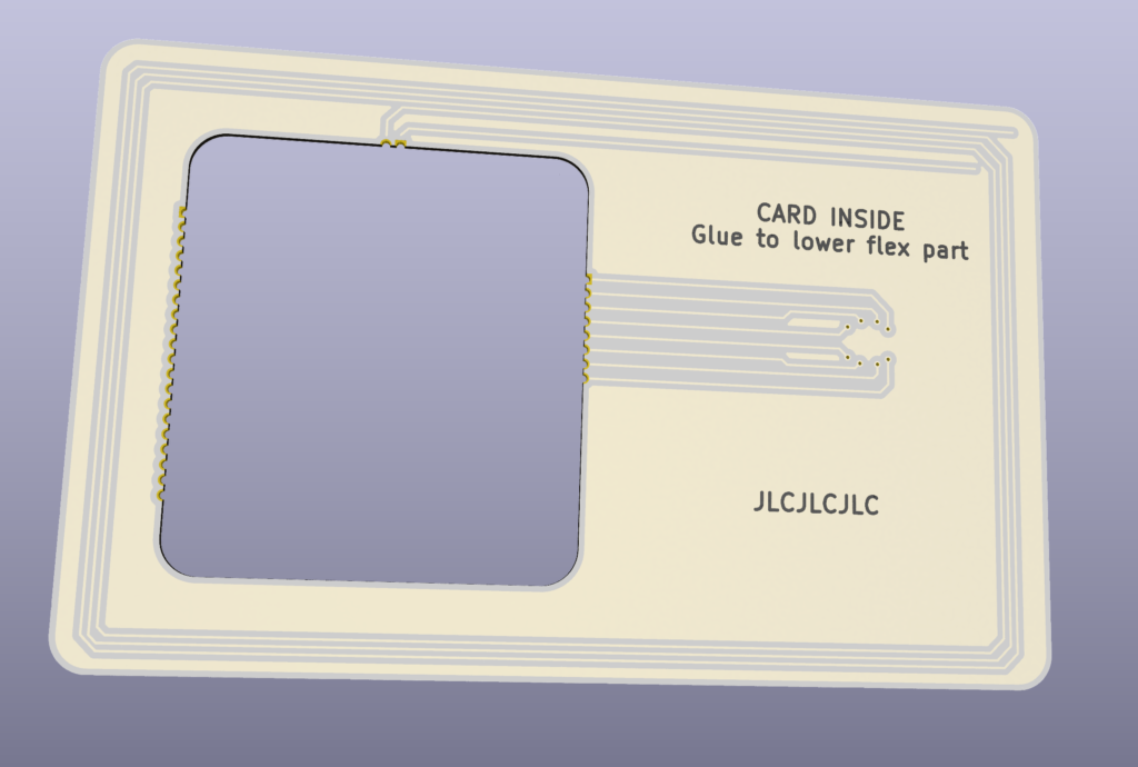
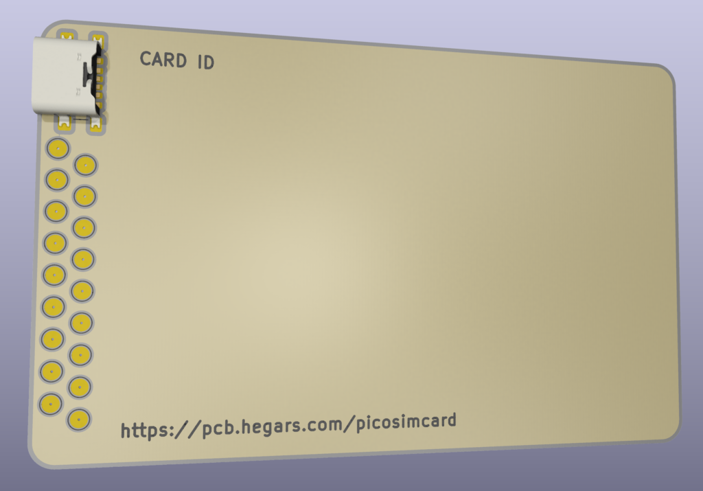
18 Pin test points breakout on the back of the card aslo an optional usb-c pad (also usb via c4 and c8 on sim slot)

Electrical
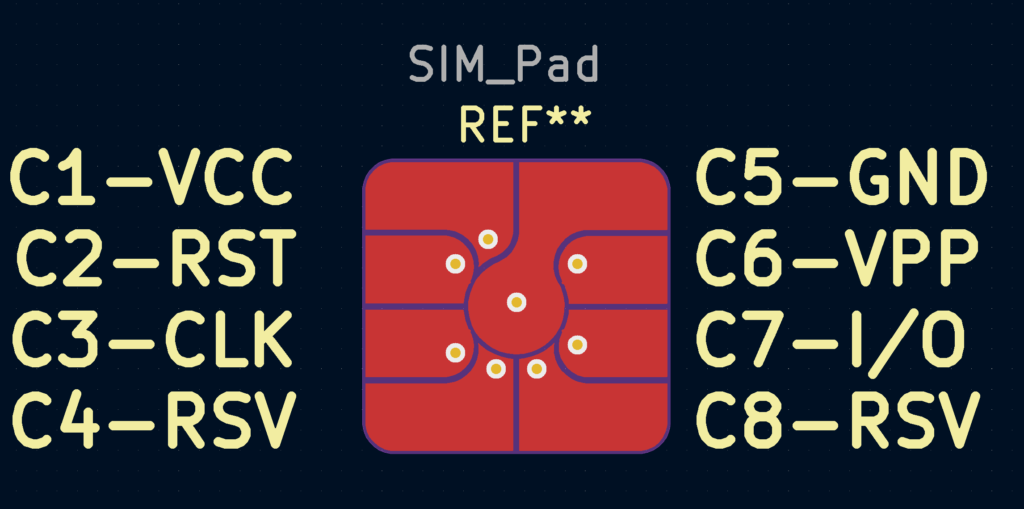
USB will be available via c4 and c8
Antenna? Possible?
