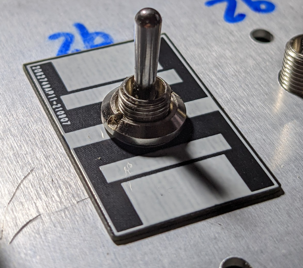
The problem I’m trying to solve is to allow for the detection and use of the center position on the SALECOM T80-T three pin series switches.
Normally in the center position of these 3 pin switches pin 2 is totally disconnected in that position where as in position 1,2 or 2,3 are related to up and down positions.
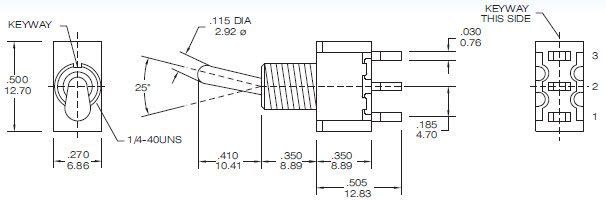
https://www.salecom.com/en/product/Miniature-Toggle-Switch-SP/t8013.html
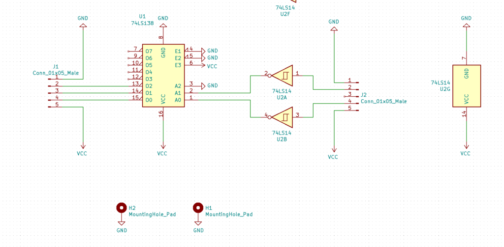
By setting a pull up or pull down arrangement on the main switch board for pin 1 and 3, I can then use a binary decoder using 74138 logic on a separate mezzanine board to output the discrete logic states for each position, 00, 01 and 10 corresponding to Center, Up and Down.
Alternately the ability to use a micro controller mezzanine board to do the same decoding, basic processing and allow for connection to digital buses.
Switch de-bouncing is handled using single stage Schmitt trigger invertor on the mezzanine board using 7414 logic (v2 will use dual invertors as there are 6 available on the chip)
Also the design of the main switch board allows for unadulterated access to all pins on the switch if the use case requires via standard 2.54mm pins.
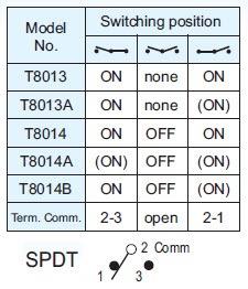
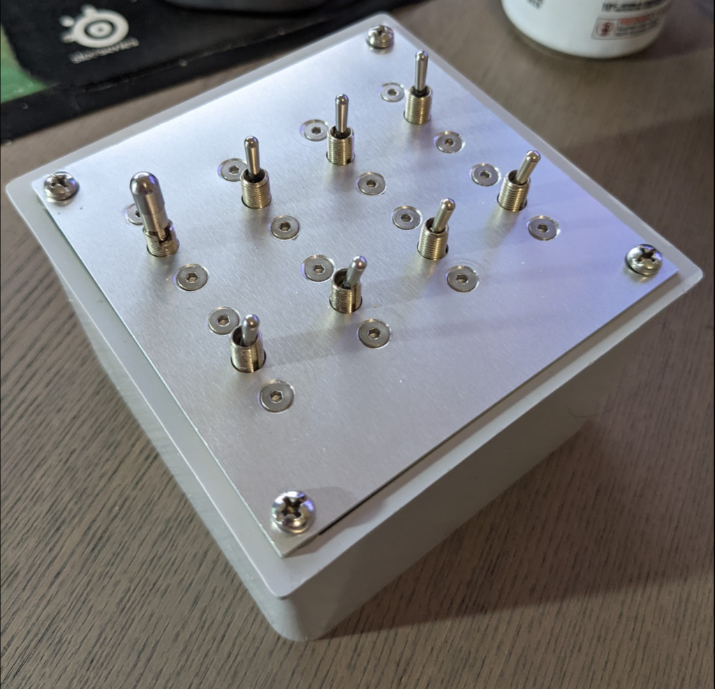
The switches used on my demo board are the
1 x T8013 (ON-none-ON)
1 x T8013 pcb pin style (ON-none-ON)
2 x Fake T8013 like switches (the SALECOM are far superior in feel, quality and probably durability)
1 x T8014 (ON-OFF-ON)
1 x T8014A (MOM-OFF-MOM)
1 x T8014B (ON-OFF-MOM)
and a locking 1 x T8014-LK (LockKON-LockOFF-LockON)
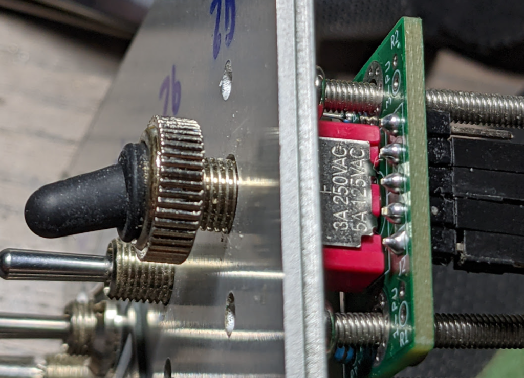
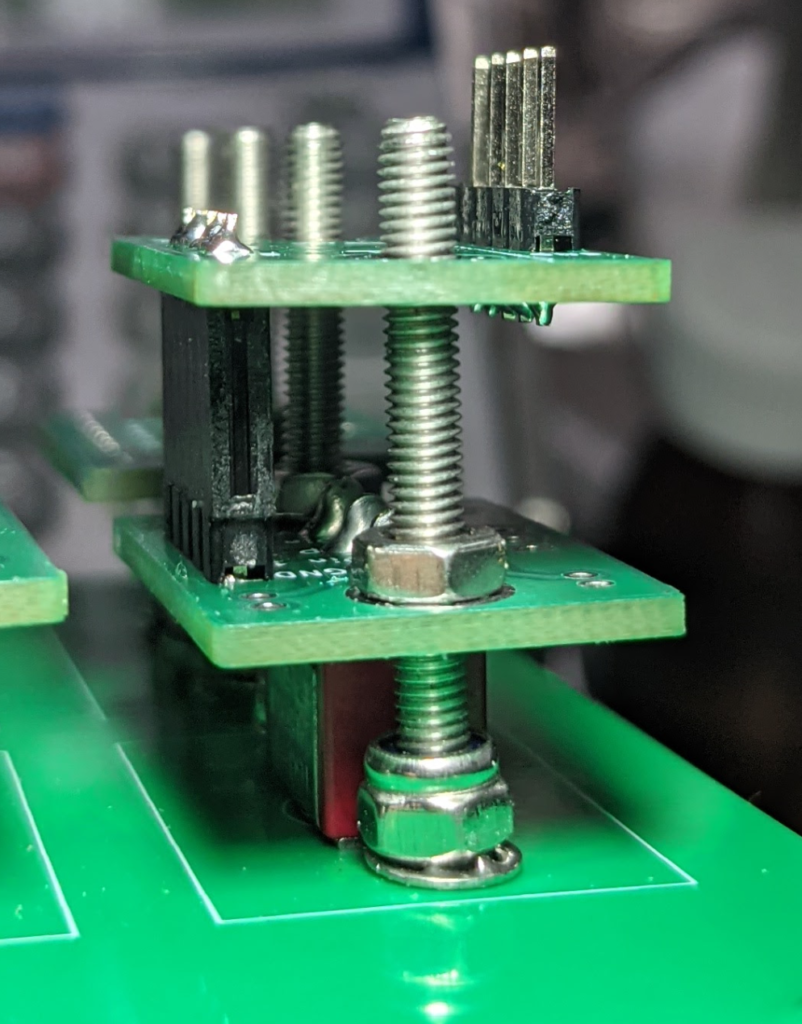
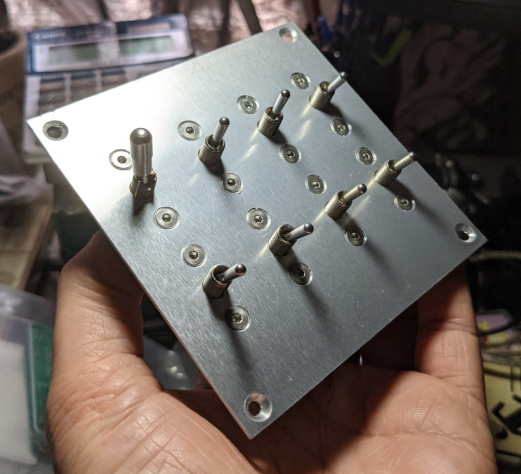
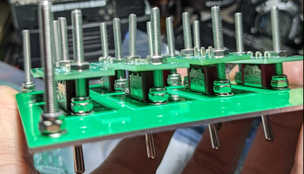
The mechanical support for the switch is tethered to the front panel by two 30mm M3 machine screws using rear locking nuts, This allows for independently secure, non rotational and non panel keyed mounting.
The design allows for easy replaceability and serviceability. It does not require any exterior nuts to secure the switch and allows unrestricted access for the waterproof cap to be installed should they be required.
Accessories
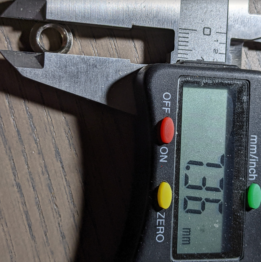
Dress Nut
M4? flanged 1.6mm ish deep?

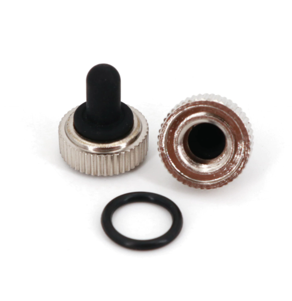
Dust Cap
The Dust Cap only screws on slight the way down which need to be considered in design, it however dose not fit prefectly into this design.
Source Code
https://github.com/hegars/BasicSwitchBO
go nuts
Main Switch Board
Features
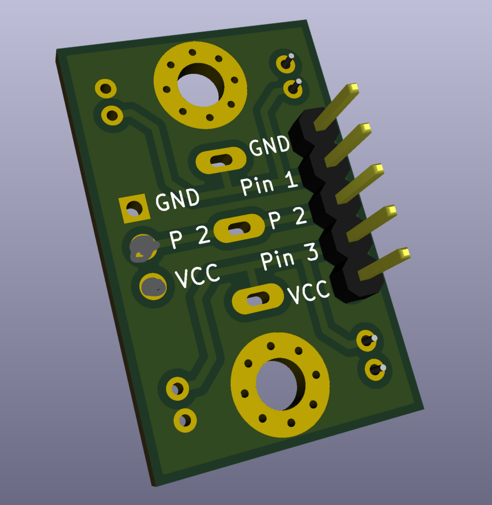
Simple 2.54mm pin access to all pins plus access to VCC and GND
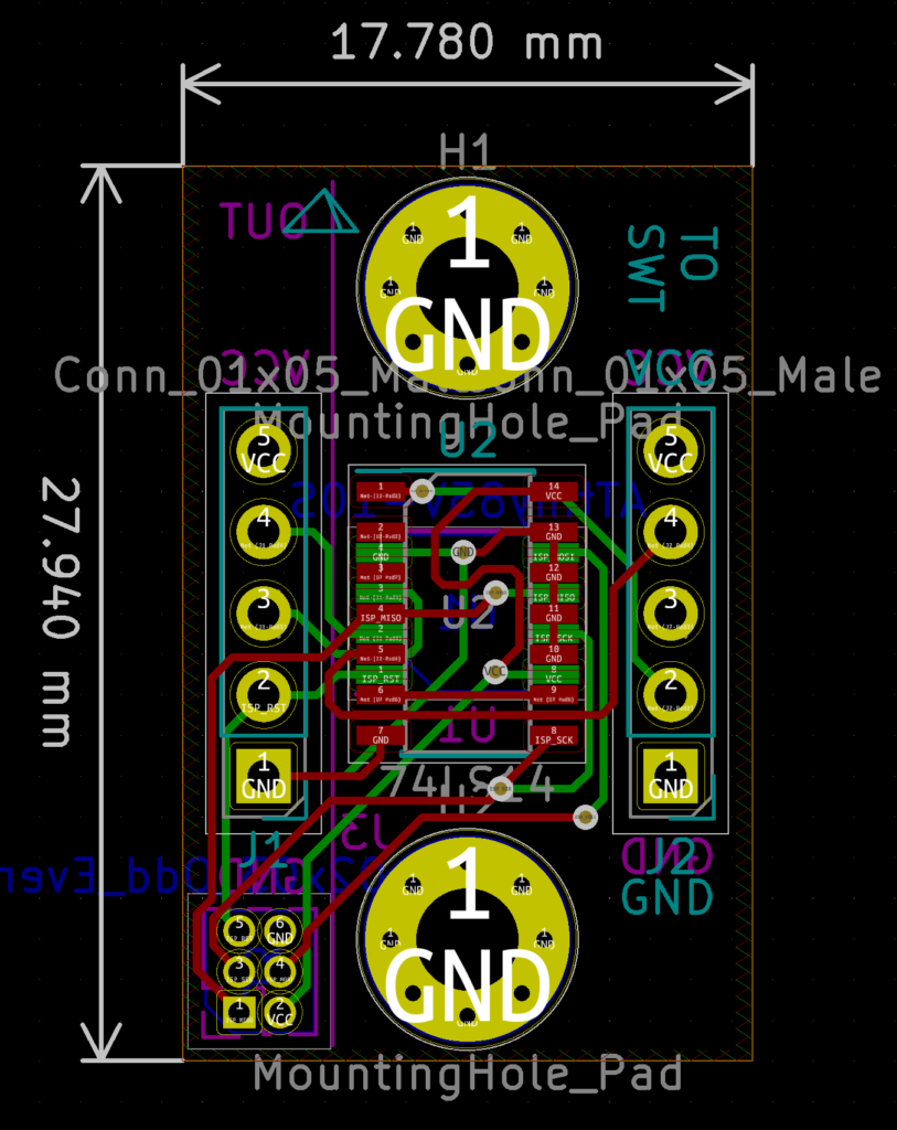
17.7mm x 27.9mm PCB
Access to Raw Pins or Option to setup for Pull up or Pull down operation
Excellent mechanical connection no rotation, no external nuts
M3 mounting holes at 20.3mm centers
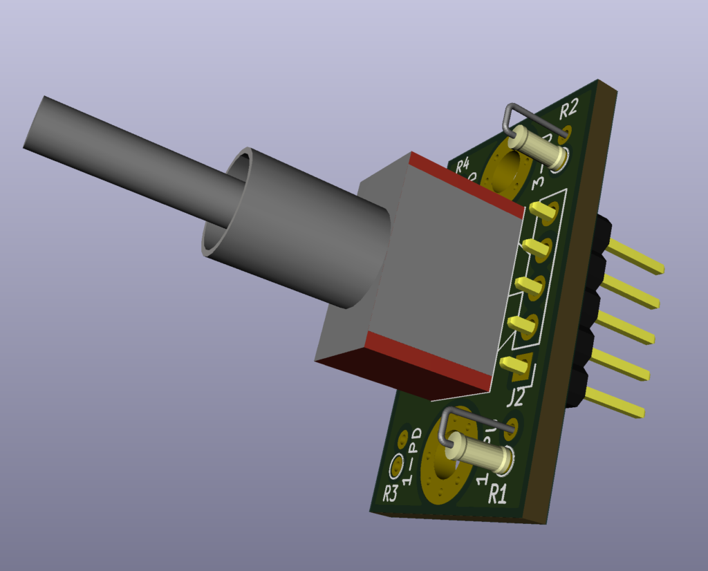
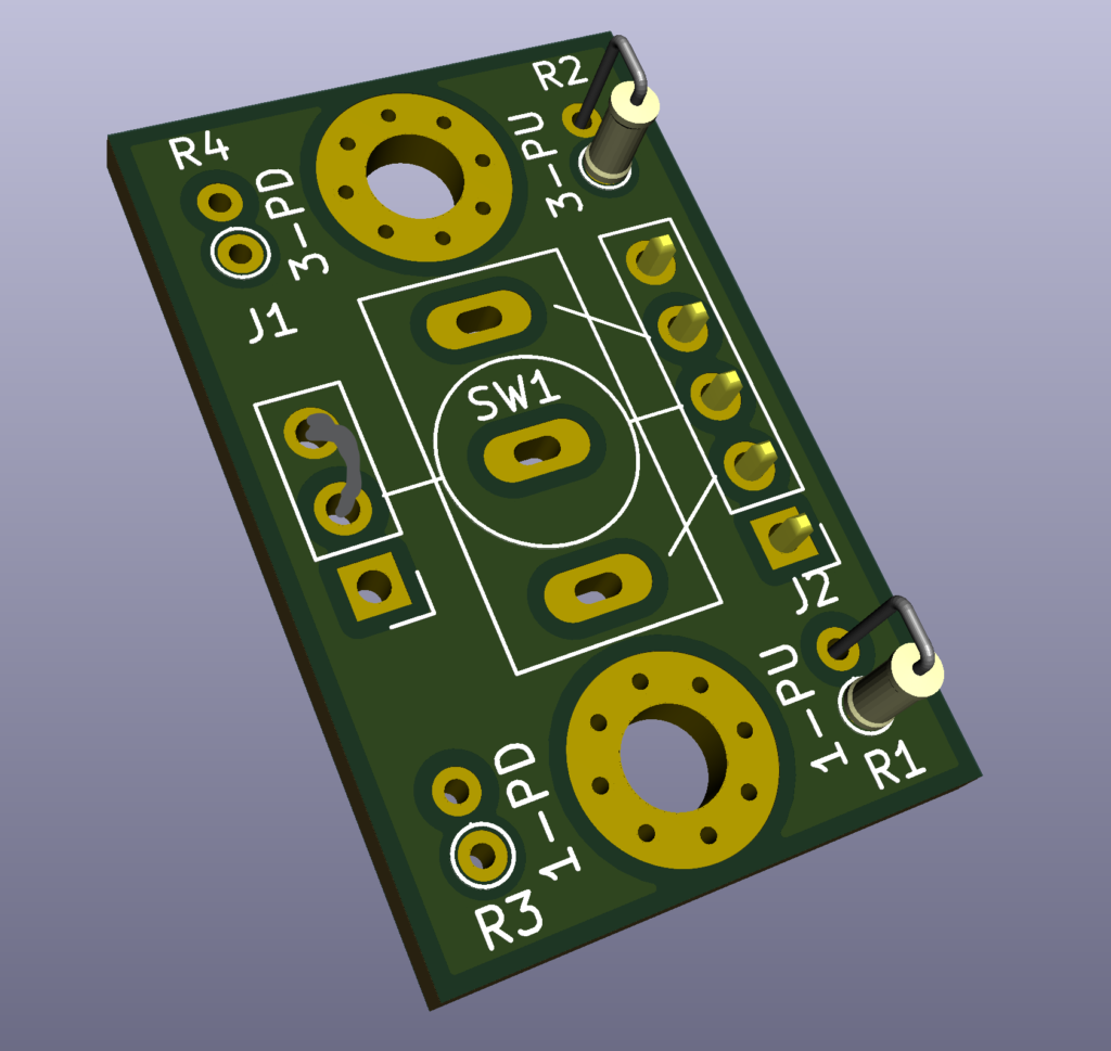
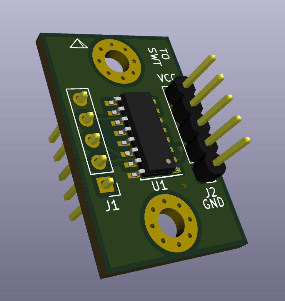
3D Render
link coming
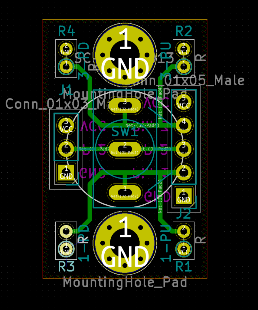
Main Switch Board Layout
PCB Layout
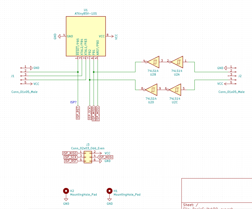
Schematics
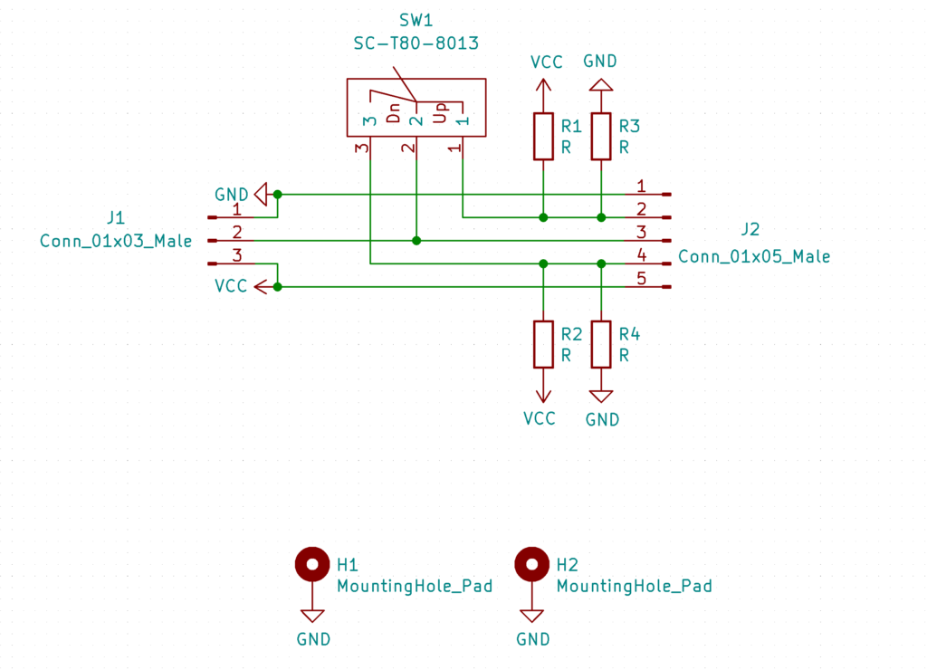
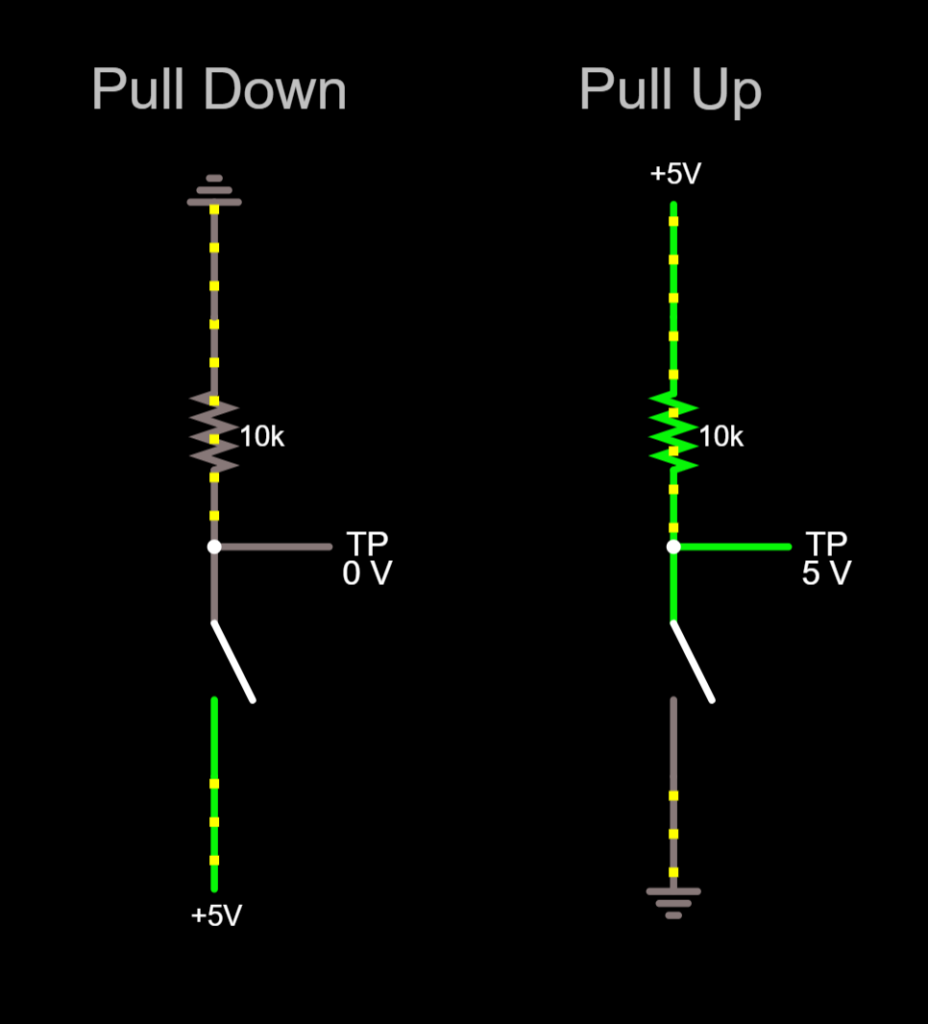
Setup of Pull up/down
Add resistors to the selected mode and connect J1 to the required power plane
Simulations of PU PD
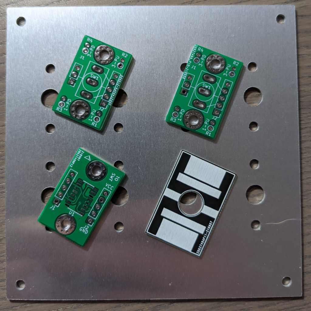
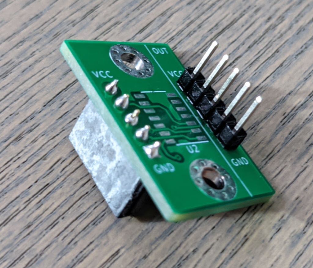
IRL
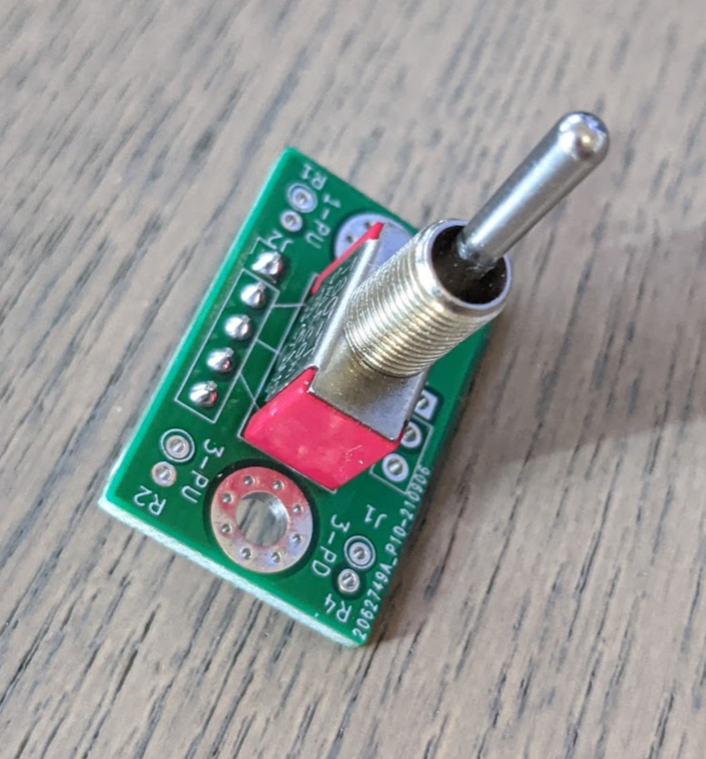
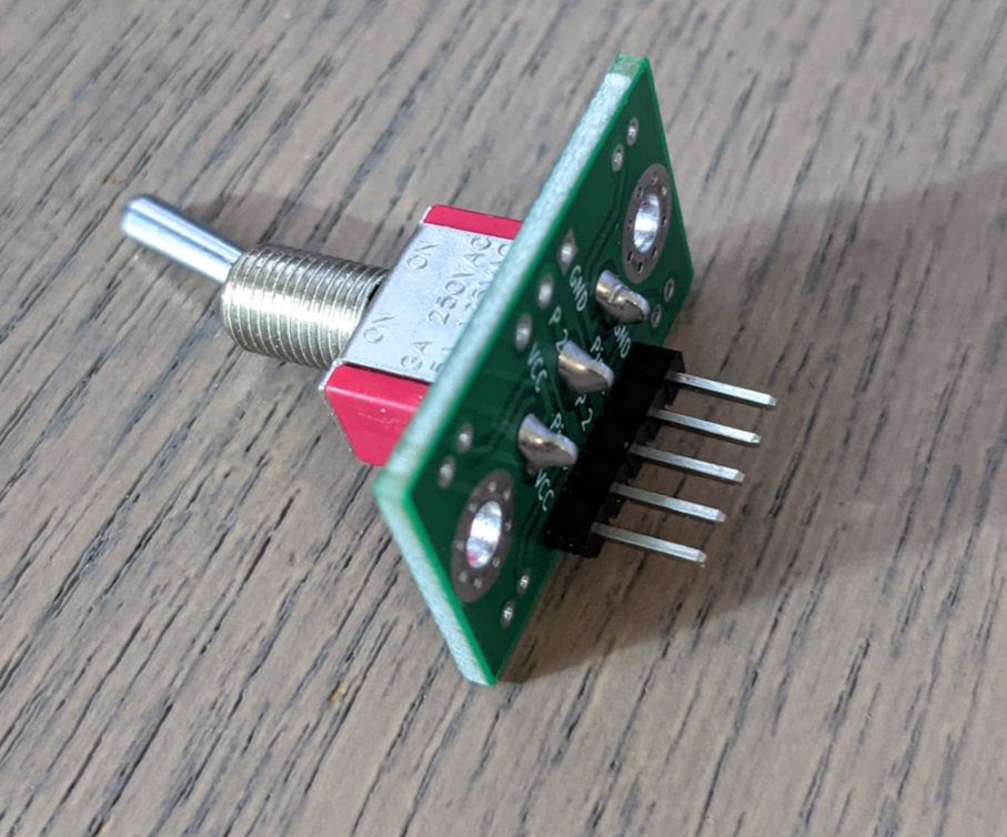
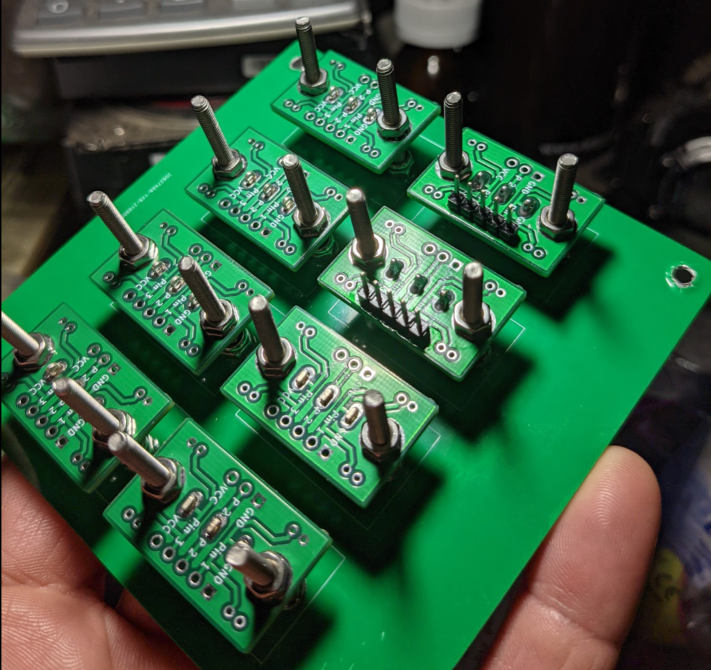
Boards
All of the Boards Together
Logic De-bounce and Decode Mezzanine Board
Logic board stacks on top of the Switch Board and filters and convers the Binary output from the switch to three logic states.
Mezzanine Mounting
Micro Controller Mezzanine Board
As an alternate to the logic board the uC board can be integrated
Dual schmitt trigger invertor input for debounce
Distribution Board
Work in progress
Handles the 24 discrete inputs and rolls it up onto the I2C bus
using the interrupts to alert position change
3 by 16 i2c expanders
8 x 5 way connectors
24 x inputs
8 x Aux I/O
16 x outputs
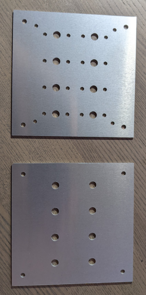
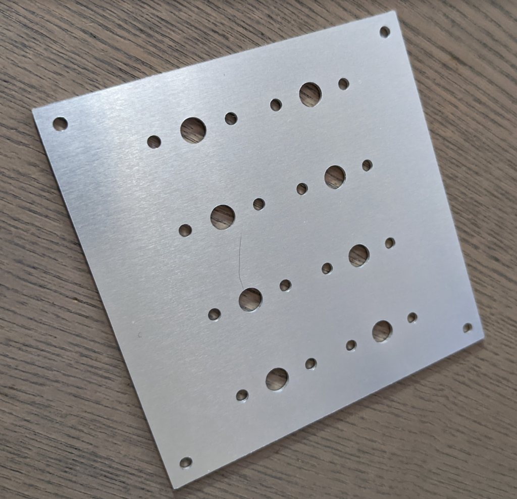
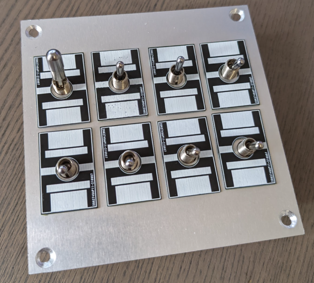
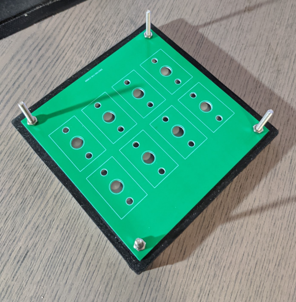
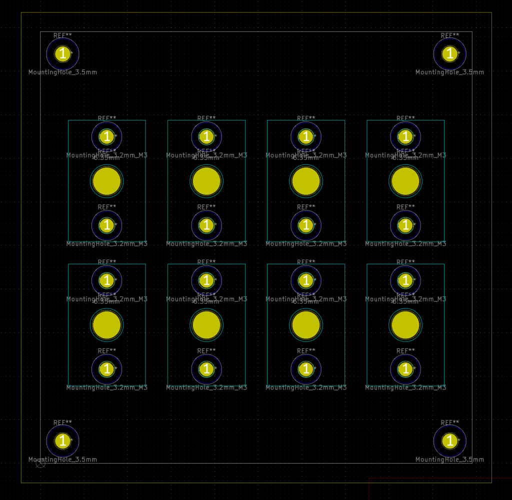
Front Panel
Produced in 1.6mm Aluminum PCB 100x100mm
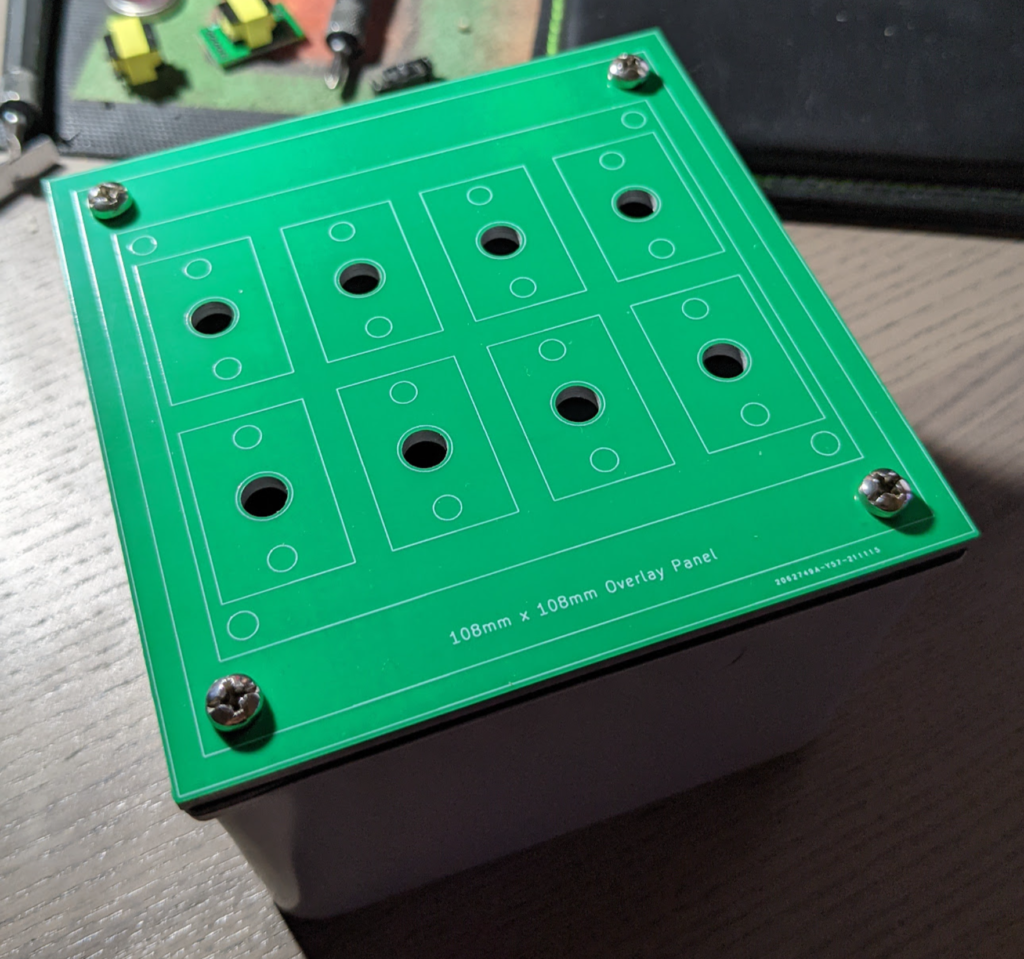
Label Overlay Boards
0.8mm PCBs to cover the screws and allow for labeling of switches.
Final Assembly
Countersinking..
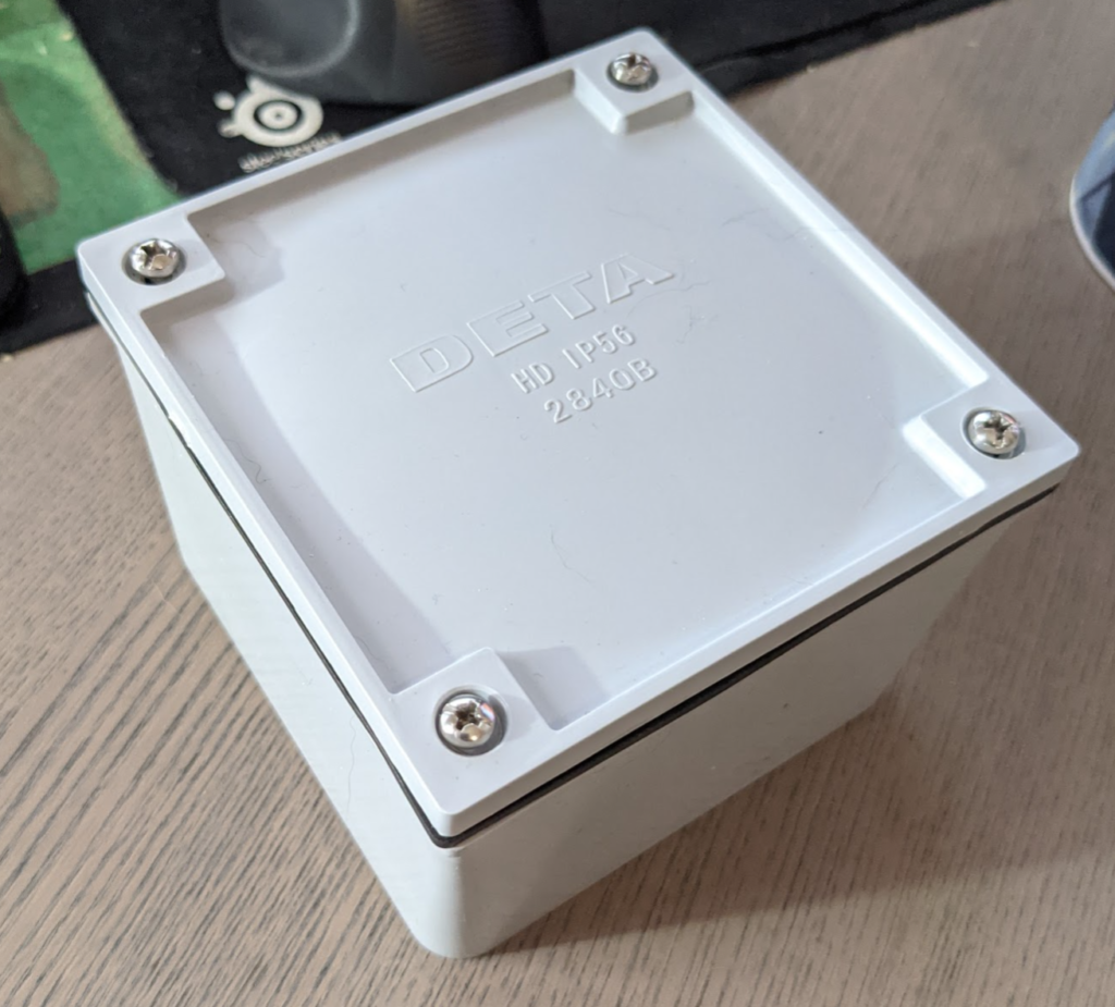
Mounting into a box
Although this was an afterthought only slight changes need to be made to extend the 100x100mm Front panel to allow it to mount into a standard and cheap 108x108x76mm electrical box.
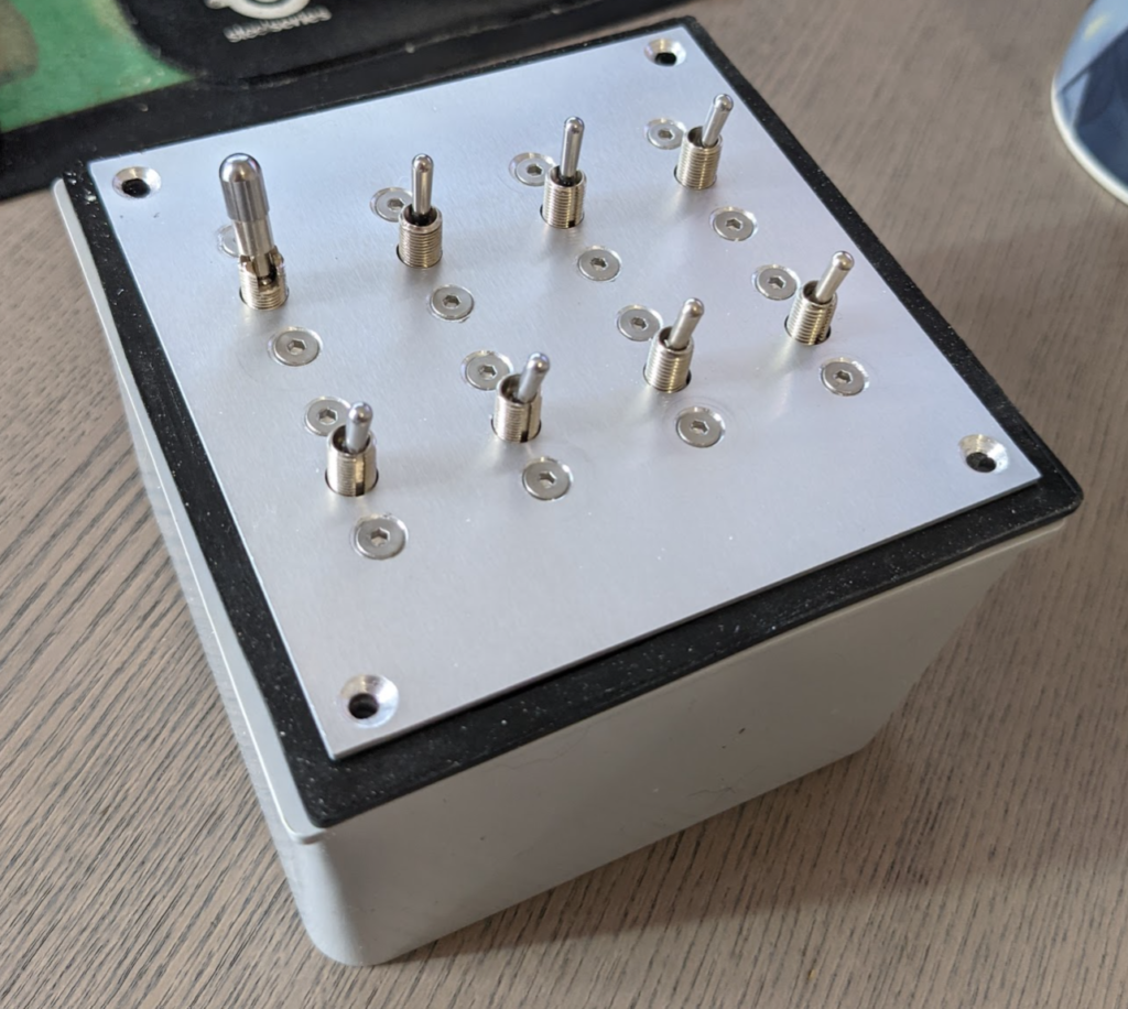
Accidental design
screw holes line up correctly huh
All I need is the additional 4mm boarder and it will fit perfectly and allow it to seal, so I mod-ed the board to 108mm2 and changed the mounting holes screws to 3.5mm to matched provided screws
Redesign
+ Add 4mm boarder to accommodate enclosure